Pi attenuator calculator (pi attenuator, attenuator pi calculator)
The Pi Attenuator Calculator helps determine the resistance values needed to design a Pi attenuator based on the desired attenuation and system impedance.
This tool is useful for RF engineers and technicians who work on attenuation circuits and signal networks.
Formula used
For a Pi attenuator:
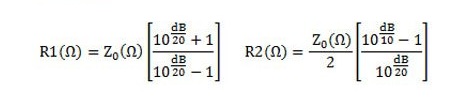
R1 = Z₀ × (K + 1) / (K – 1) (shunt)
R2 = Z₀ × (K² – 1) / (2 × K) (series)
where K = 10^(A / 20)
Explanation
R1 is the shunt resistance, R2 is the series resistance. Z₀ is the system impedance, and A is the desired attenuation in dB.
The constant K represents the linear voltage ratio corresponding to the desired attenuation. These formulas allow resistance values to be precisely calculated to obtain the exact attenuation without disturbing the system impedance.
Calculation example
For an attenuator with:
A = 6 dB , Z₀ = 50 Ω :
K = 10^(6/20) ≈ 1.995
R1 = 50 × (1.995 + 1) / (1.995 – 1) ≈ 200.0 Ω
R2 = 50 × (1.995² – 1) / (2 × 1.995) ≈ 49.9 Ω
Benefits and Use
- Allows you to quickly design a Pi attenuator for any desired attenuation level.
- Maintains system impedance to avoid reflections and signal losses.
- Useful for adjusting signal levels in RF circuits and communications systems.
- Optimizes the performance of attenuation networks in RF, audio and electronics applications.